|
2.1 Introduction |
The BIOpolymer Markup Language is being designed to meet
or exceed a number of goals that are critical for the development and
acceptance of the language. BIOML must:
-
be extensibile, i.e., it should conform to the
XML
format;
-
be a faithful representation of the concept being described (protein/gene);
-
have the potential to be easily read by humans;
-
logically connect every element in a clearly expressed statement nesting
structure;
-
include data that is not ASCII and support compression as a basic data type;
and
-
support the conversion of other data files to and from BIOML.
|
|
These goals are laid out in order of importance. If any consideration affects
one higher on the list, then the higher priority goal will prevail in any
argument. The ability to logically connect data to a physical object's
individual parts is a the main driving force behind the development of BIOML.
|
|
2.2 Logical layout–trees, branches and leaves |
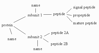
The diagram below shows a simple graphical relationship between a simple set of
objects that can be associated with a "protein" object.
|
|
The fundamental object (a protein) is connected to two branch objects
(its component pieces, subunit 1 and subunit 2) and one leaf
object (its name). The first of the branches (subunit 1) is
connected to another branch object (a peptide), which has a number of
leaf objects associated with it. The linear nature of peptide and
oligonucleotide biopolymers and the way that information about them has been
gathered and organized makes it possible to draw such a graph for almost every
concievable attribute and annotation of the biopolymer. BIOML is being designed
to take advantage of this fact.
|
|
2.3 Logical layout using nested statements |
The problem of writing down branched structures has been dealt with by computer
scientists in a number of ways. The method used in XML is a very
straightforward one. Using the example above, the protein is represented by an
opening "tag" represented by "<protein>" and a closing tag "</protein>".
Everything within those two tags is part of the tree illustrated above. Using
this notation, the tree can be re-written as follows:
<protein>
    <name> ... </name>
    <subunit id="1">
        <name> ... </name>
        <peptide>
            <signal> ... </signal>
            <propeptide> ... <propeptide>
            ...
        </peptide>
    </subunit>
    <subunit id="2">
        <name> ... </name>
        <peptide id="1">
            ...
        </peptide>
        <peptide id="2">
            ...
        </peptide>
    </subunit>
</protein>
All of the relationships between items are the same as in the tree, but this
format is very easy to write out using ASCII characters. The ellipsis "..."
symbols represent any text that might be enclosed by the start and end tags. In
the language of XML, the ideas that are represented by "protein" or "name" are
called elements, while the symbols that are used to represent the start
and end of the pieces of information that make up the element are called
"tags".
|
1. Bioinformatics
|
TOC
|
3. Elements and tags
|
|